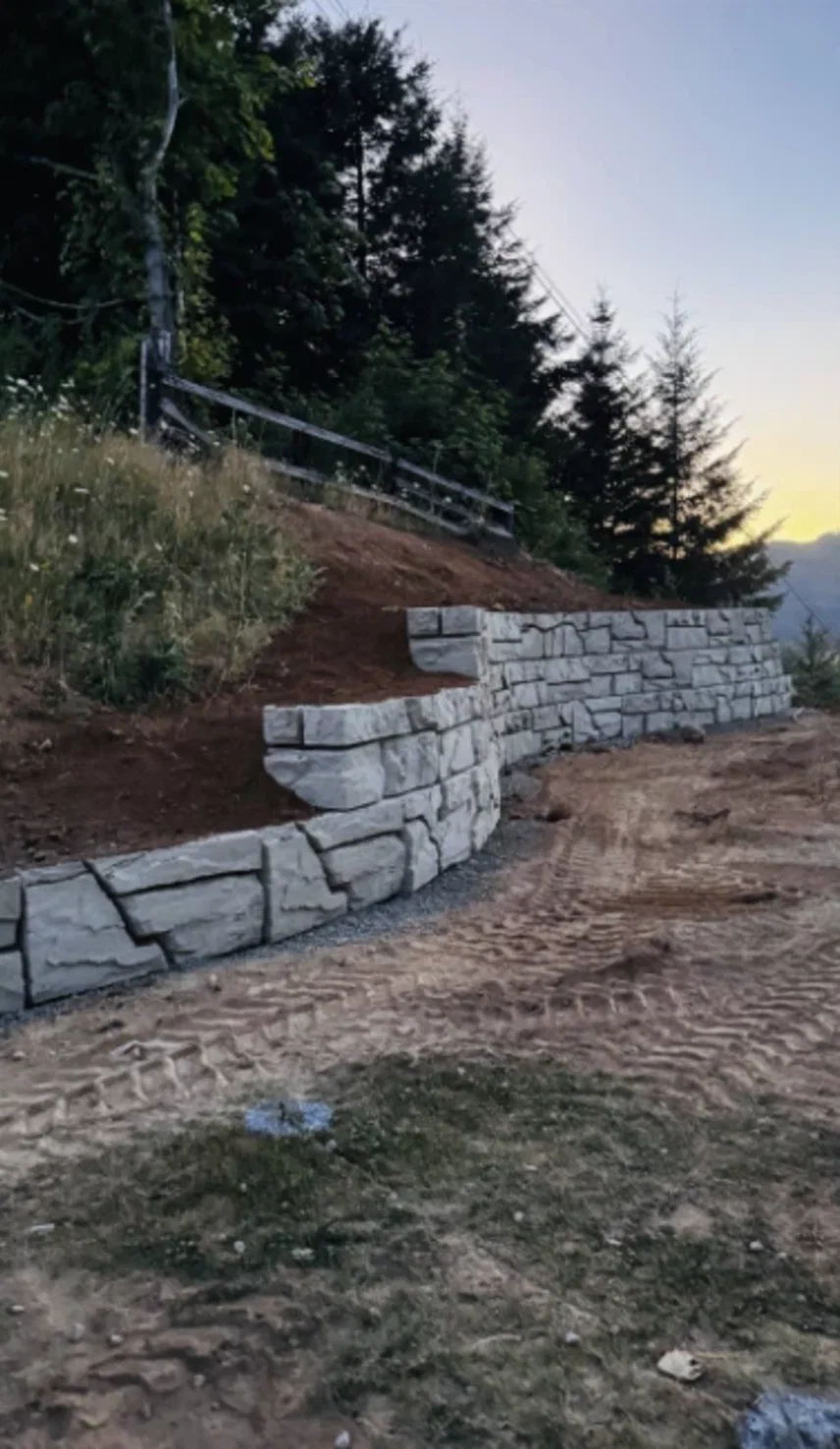
Standard unit: dimensions and weight
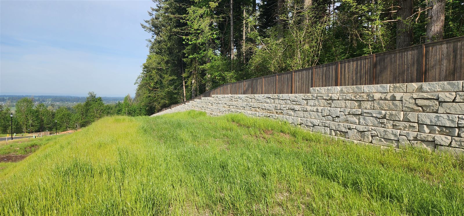
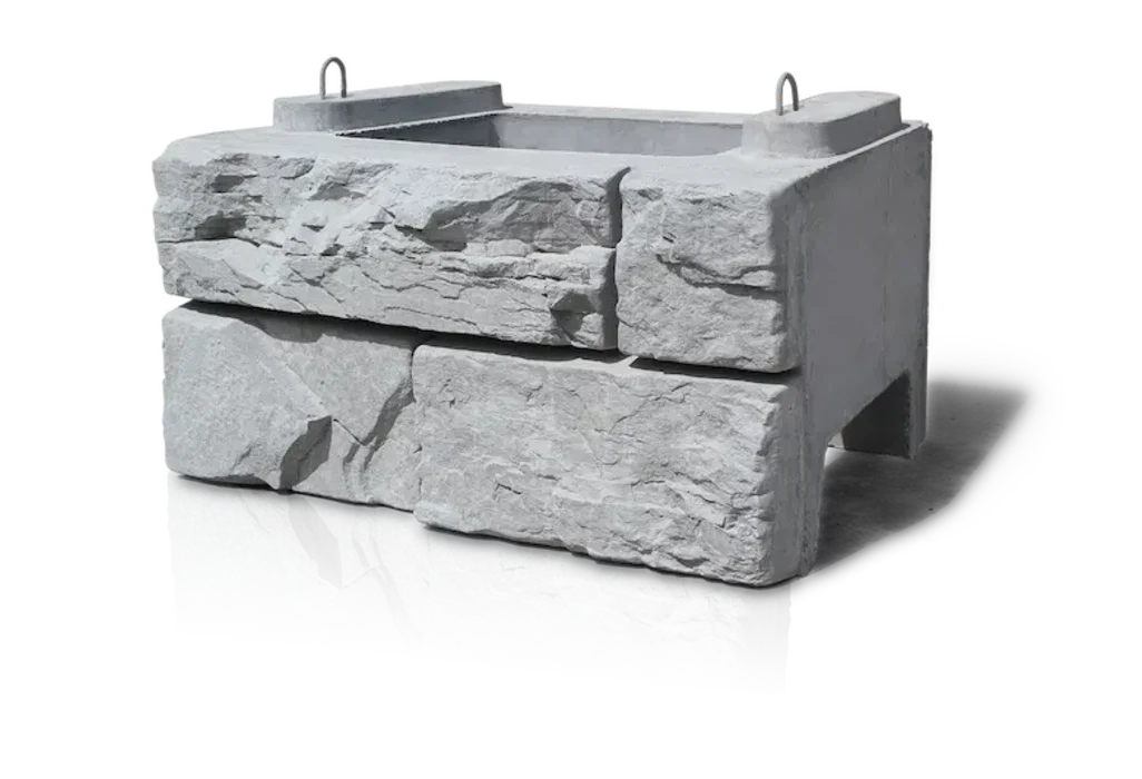
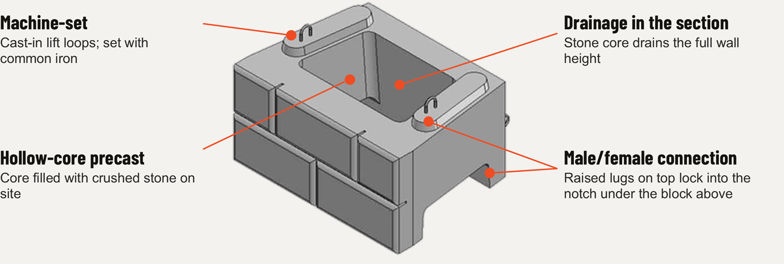
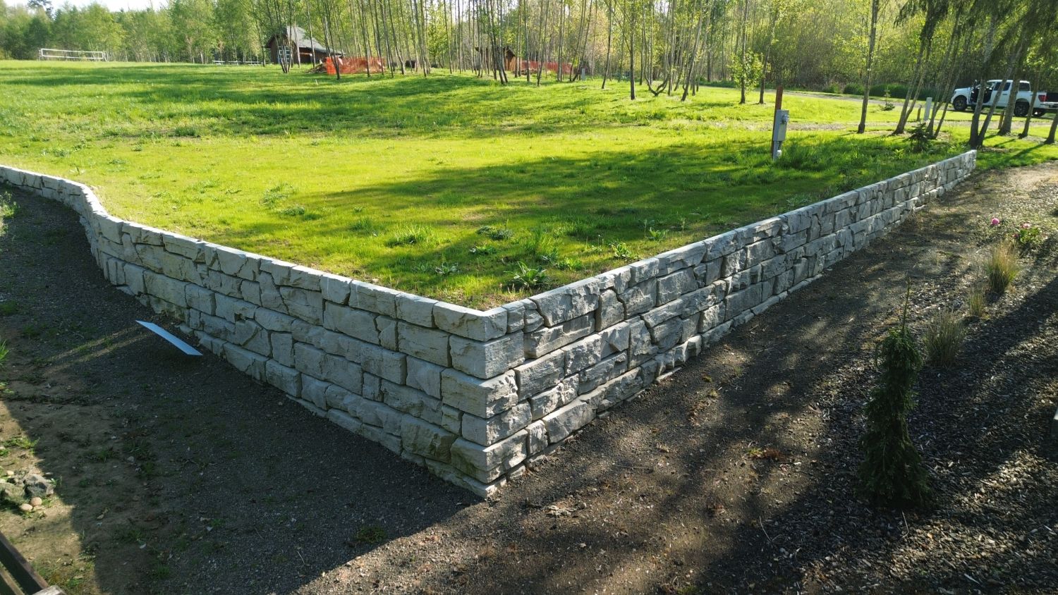
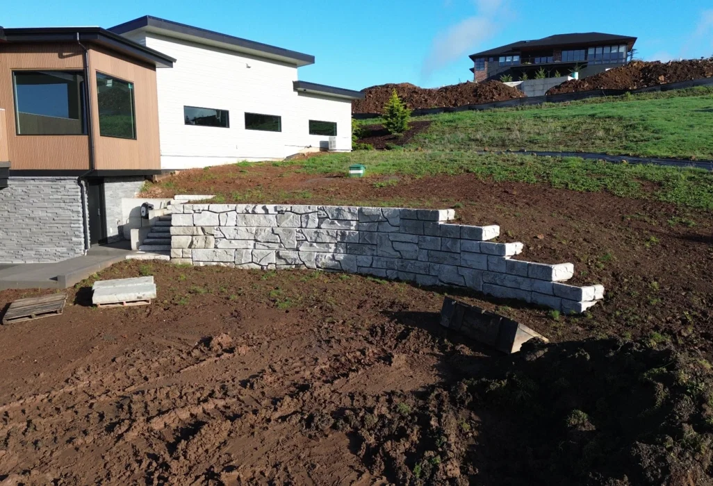
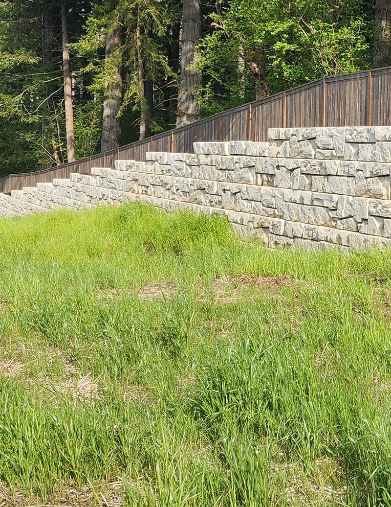
The standard block makes up about 90% of a typical Verti-Block wall. Each unit has hollow cores, a male/female connection that sets the batter automatically on every course, and a Canyon Ledge stone face.
| Property | Value |
|---|---|
| Size | 2 ft high × 4 ft wide × 3 ft deep (8 sq ft of face) |
| Weight, empty | About 1,760 lb |
| Weight, cores filled with gravel | About 3,035 lb |
| Face | Canyon Ledge texture, 5 in. of relief |
| Standard batter | 2-3/16 in. per 24 in. course (about 5°) |
| Setback option | 12 in. per course (about 26°) |
| Zero-batter option | Shear-lug blockouts (detail WD-31) |
| Minimum curve radius | 16 ft |
| Tolerances | Height ±1/8 in.; width and depth ±1/2 in. |
| Freeze-thaw | ASTM C666, or an approved DOT mix |
In plain terms Each standard block covers 8 sq ft of wall face. A wall 4 ft high and 40 ft long is 2 courses of 10 blocks: about 20 blocks.
The Verti-Block family
Every wall is built from a handful of shapes. The standard block does most of the work; the others handle ends, corners, the top course, height changes and the base.
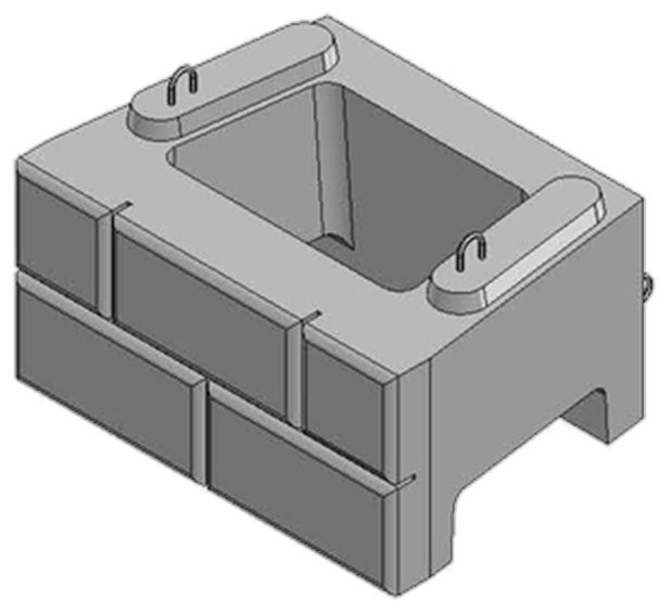 StandardAbout 90% of a wall · 1,760 lb
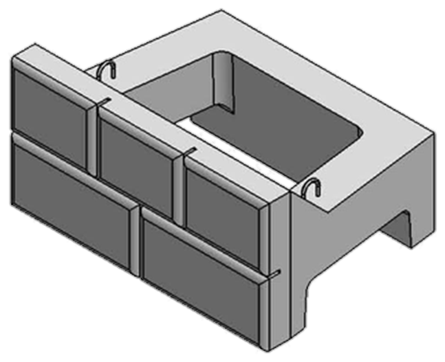 TopLets soil and grass run over the wall · 1,312 lb
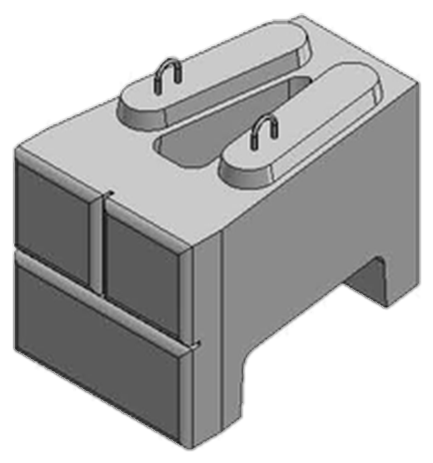 HalfWall ends, every other course · 1,070 lb
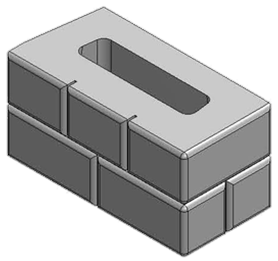 Corner90° outside corners · 1,600 lb
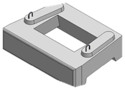 Half-step1 ft height changes · 970 lb
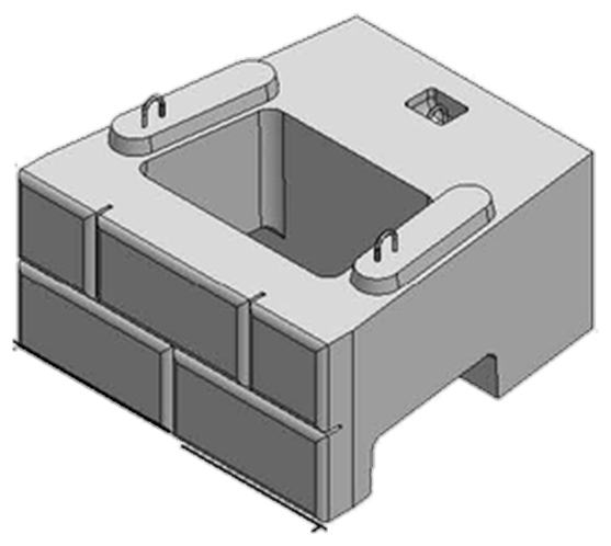 Mass extenderBase courses of tall walls · 2,674 to 5,098 lb
| Unit | Size | Approx. weight | Used for |
|---|---|---|---|
| Standard | 4 × 2 ft face, 3 ft deep | 1,760 lb | About 90% of a wall |
| Top | 4 × 2 ft face, soil cutout at the back | 1,312 lb | Top course; soil and grass run over the wall |
| Half | 2 × 2 ft face, 3 ft deep | 1,070 lb | Wall ends, every other course |
| Corner | 4 × 2 ft face plus a finished 2 × 2 ft return | 1,600 lb | 90° outside corners (45° options available) |
| Half-step | 4 × 1 ft face | 970 lb | 1 ft height changes and exact heights |
| Mass extender | 48 to 84 in. deep | 2,674 to 5,098 lb | Base courses of taller gravity walls |
Design basis and material properties
- Concrete: 142 pcf design unit weight; about 4,000 psi at 28 days.
- Core fill: gravel at 110 pcf. Combined block and fill: about 126 to 131 pcf (composite design weight 126 pcf, 24.0 cu ft, center of gravity 18.14 in.).
- Retained soil assumed in the tables: 120 pcf.
- Factors of safety in the published tables: sliding 1.5, bearing 2.0. Overturning and other criteria are set in the site-specific design.
- Minimum embedment: H/10, and never less than 6 in.
- Leveling pad concrete, if used: 3,000 psi minimum.
- Methodology: NCMA (3rd Edition) and AASHTO LRFD.
How tall can a Verti-Block gravity wall be?
Without any geogrid, published gravity heights run from 5.5 ft to 19 ft at the standard 5° batter with mass-extender base courses. The range depends on how strong the retained soil is, whether there is a surcharge (like a parking lot or a building) above the wall, and whether the ground slopes up behind it.
| Retained soil (friction angle) | Level, no surcharge | Level, 250 psf surcharge | 2:1 sloping backfill |
|---|---|---|---|
| Silty (≥ 28°) | 7.5 to 13 ft | 5.5 to 11 ft | 5.5 to 7.5 ft |
| Sandy (≥ 30°) | 7.5 to 15 ft | 5.5 to 11 ft | 5.5 to 9.5 ft |
| Gravelly sand (≥ 35°) | 9.5 to 17 ft | 7.5 to 15 ft | 9.5 to 15 ft |
| Gravelly (≥ 40°) | 11 to 19 ft | 9.5 to 17 ft | 11 to 17 ft |
In plain terms In good gravelly soil, the published tables show a Verti-Block wall holding back up to 19 ft of ground with no geogrid at all: just the weight of the blocks and the stone in their cores.
The published gravity tables do not include seismic loading. The free Verti-Block analysis software runs seismic and global-stability checks for a site-specific design.
Standard batter vs. the 12-inch setback
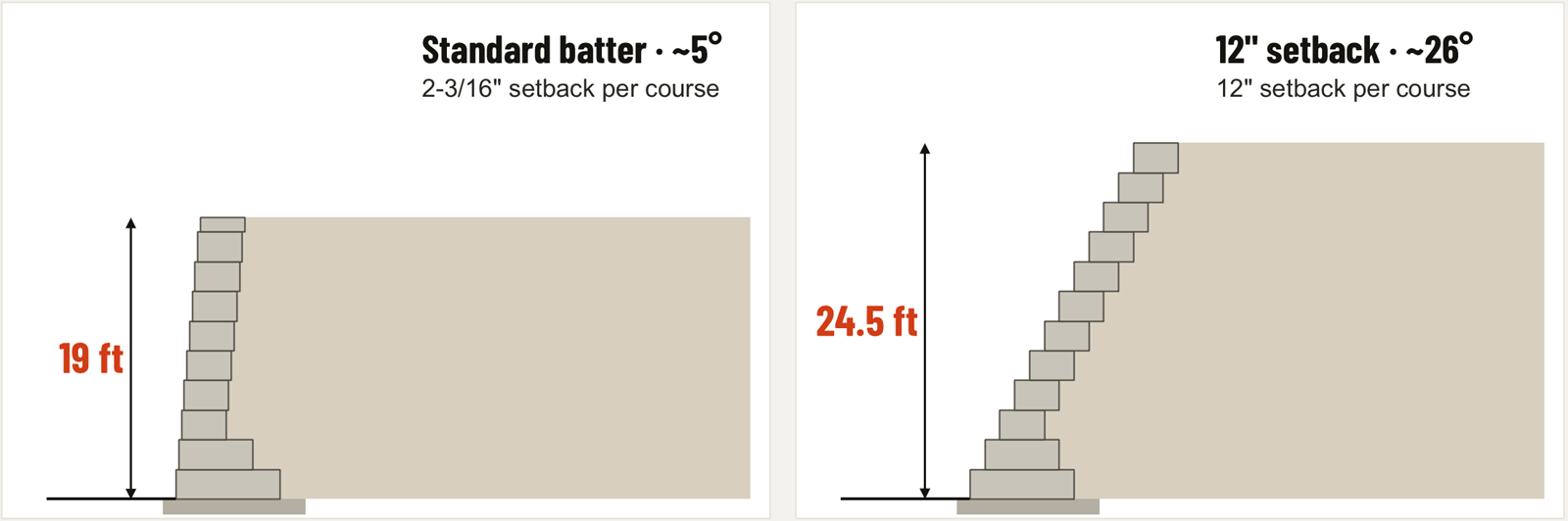
Laying each course back 12 in. (about a 26° batter) instead of the standard 2-3/16 in. (about 5°) lets a gravity wall go taller. In gravelly soil with mass extenders, the published height goes from 19 ft at the standard batter to 24.5 ft with the setback: about 5.5 ft more wall, gained through geometry instead of reinforcement. The trade-off is 12 in. of horizontal travel per course, so the wall needs more room at the top.
Mass extenders
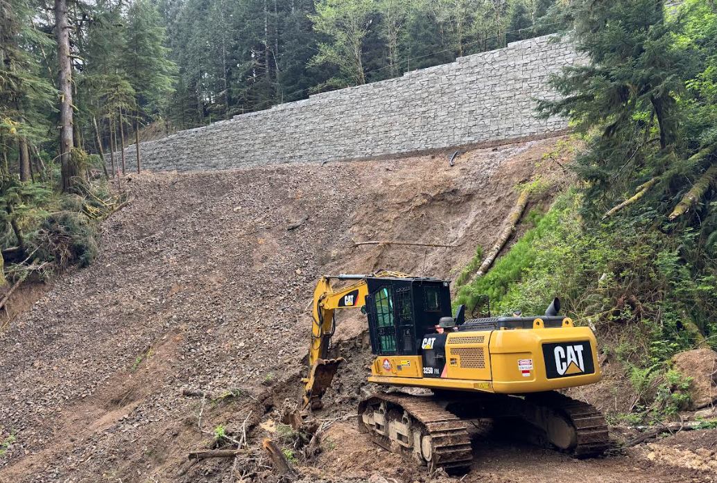
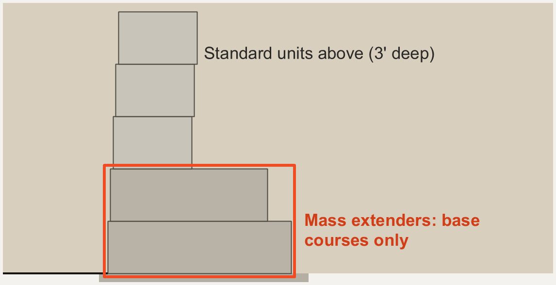
Mass extenders are deeper units for the base courses. They put weight where the overturning force on a wall is greatest, so the wall can go taller as a gravity wall, inside the same narrow footprint, without a reinforced soil zone behind it. They typically backfill with compacted native soil, so no imported structural fill is needed.
| Unit | Depth | Approx. weight |
|---|---|---|
| 48 in. mass extender | 4 ft | 2,674 lb |
| 60 in. mass extender | 5 ft | 3,509 lb |
| 60 in. dual-cavity | 5 ft | 2,783 lb |
| 72 in. mass extender | 6 ft | 4,297 lb |
| 84 in. mass extender | 7 ft | 5,098 lb |
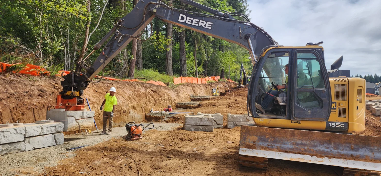
They matter most when property lines, utilities or existing structures behind the wall rule out excavating for geogrid. The heaviest unit is about 5,100 lb, so walls are still set with an excavator.
Geogrid-reinforced walls
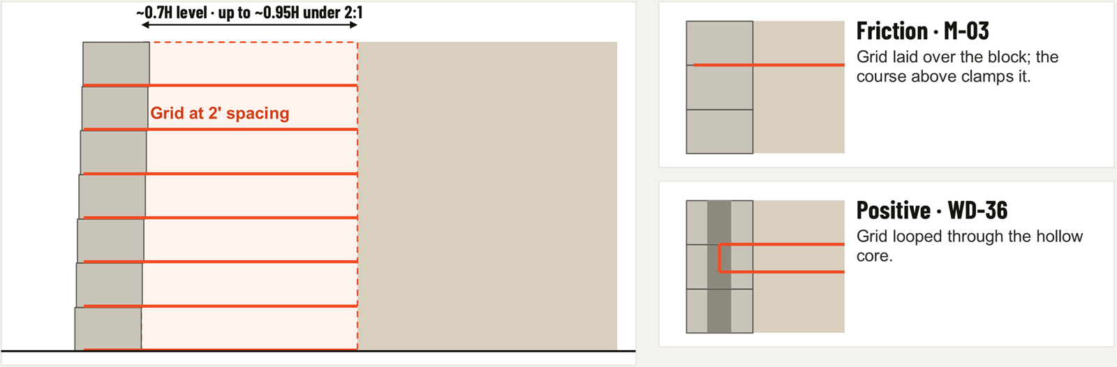
When a wall needs to go taller than gravity allows, geogrid (Stratagrid 200, 500 or 600) goes in every course at 2 ft spacing in the published designs. Grid length stays the same from top to bottom, which keeps take-offs simple.
| Retained soil (friction angle) | No geogrid up to | Max published height | Grid length at max height |
|---|---|---|---|
| Silty (≥ 28°) | 10 ft | 30 ft | 20.0 ft (Strata 600) |
| Sandy (≥ 30°) | 10 ft | 30 ft | 20.0 ft (Strata 600) |
| Gravelly sand (≥ 35°) | 12 ft | 30 ft+ | 18.0 ft (Strata 600) |
| Gravelly (≥ 40°) | 14 ft | 30 ft+ (34 ft published) | 20.4 ft (Strata 500) |
- Grid length: about 0.65 to 0.70 times the wall height on level ground, up to about 0.95 times the height under a 2:1 slope. Minimum reinforcement length is 0.7H from the face.
- Coverage: 100% horizontal coverage, at a maximum vertical spacing of 4 ft (two courses).
- Connections: friction connection with the grid laid over the block (detail M-03), or a positive connection with the grid looped through the hollow core (detail WD-36).
Drainage
The design tables assume the backfill is drained, so drainage is part of the structure, not an accessory. Four details keep that assumption true:
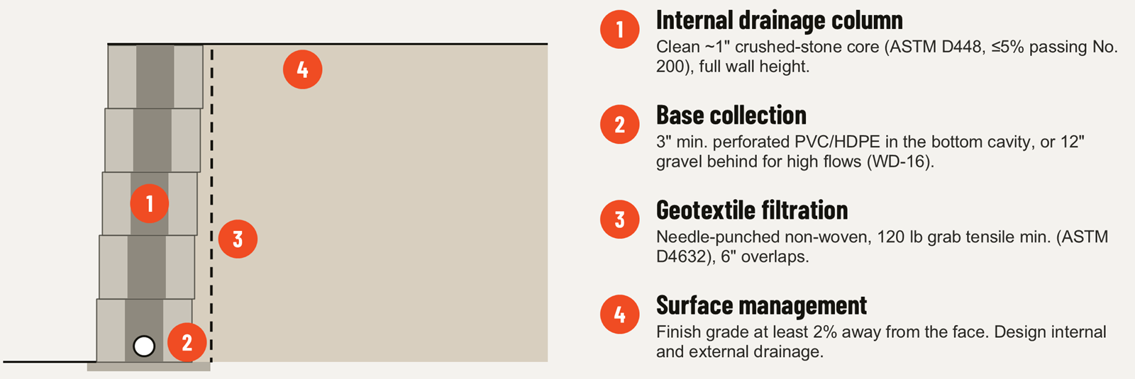
- Drainage column: clean crushed stone of about 1 in. in the cores (ASTM D448, no more than 5% passing the No. 200 sieve) forms a continuous drain the full height of the wall.
- Base collection: perforated PVC or HDPE pipe, 3 in. minimum, in the bottom block cavity, or paired with 12 in. of gravel behind the wall where flows demand it (detail WD-16).
- Filter fabric: needle-punched non-woven geotextile, 120 lb minimum grab tensile (ASTM D4632), lapped 6 in., keeps fines out of the drainage stone.
- Surface water: finish grade sloped at least 2% away from the wall face.
Installation specification points
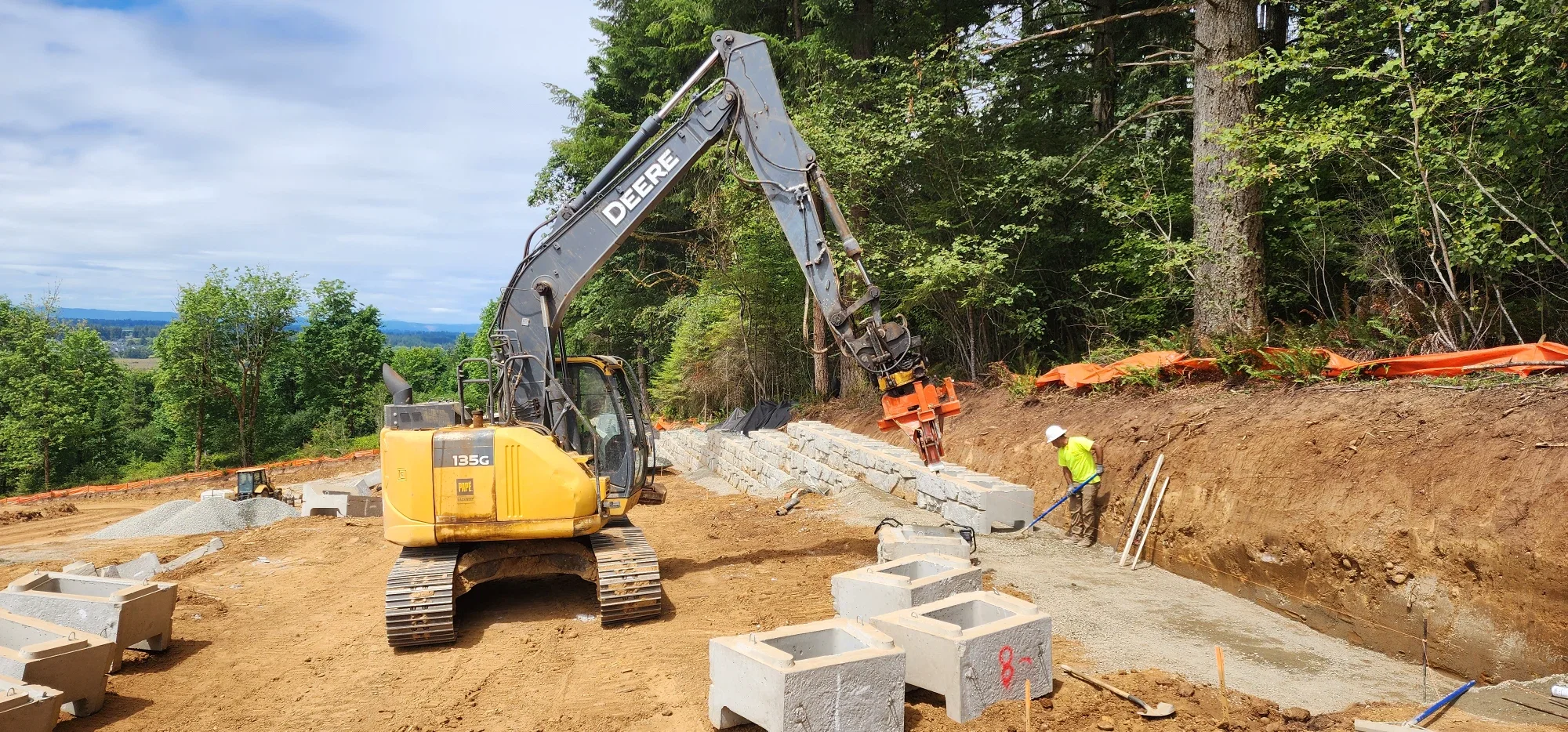
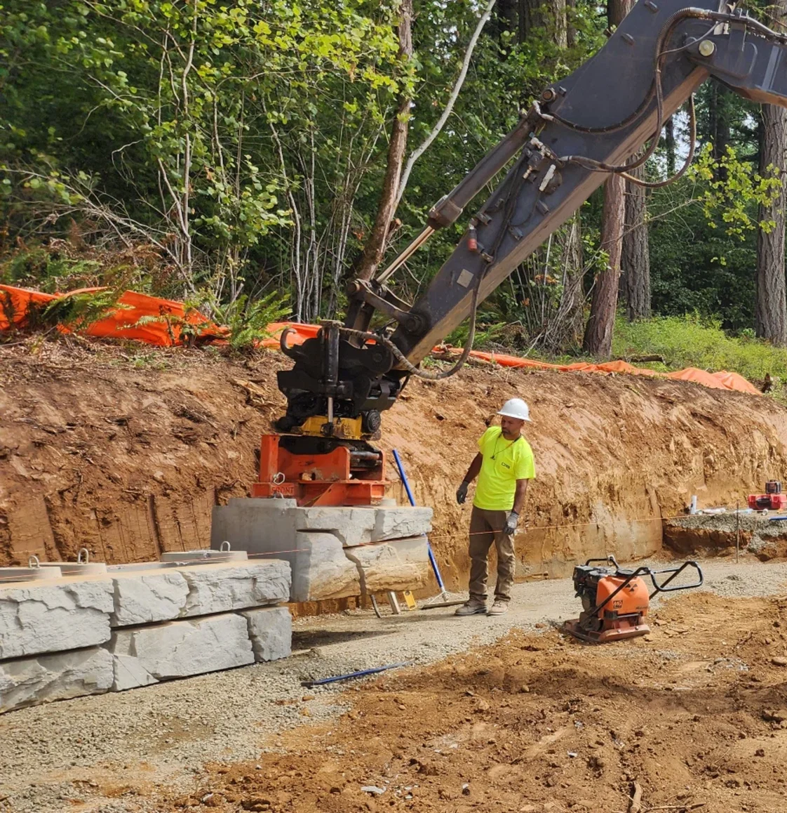
- Leveling pad: 6 in. minimum depth (12 in. where required), of crushed stone 1 ft wider than the block depth, or 3,000 psi concrete. It must be compacted, level and accepted before the first course goes down.
- Foundation: proof-rolled, with bearing soils confirmed by the geotechnical engineer and unsuitable soils replaced.
- First course: set over the drain pipe and leveled side to side and front to back. It is the critical course.
- Stacking: running bond, with each female notch set over the male riser and pulled forward to set the batter.
- Backfill soils: liquid limit under 45 and plasticity index under 20; fat clays and oversized rock excluded unless the geotechnical engineer approves.
- Compaction: lifts of 12 in. maximum to the density in the project specification, with only hand-operated compactors within 3 ft of the wall. Test at least every 2 vertical ft and every 50 lineal ft.
Design tools and support
- Free analysis and design software: gravity and reinforced design to NCMA, AASHTO ASD/LRFD and CAN-CSA, with seismic and global-stability checks, plan-to-layout conversion, block counts, geogrid schedules and CAD export. Available at verti-block.com.
- Design manual and details: the Verti-Crete Design Manual, block detail sheets (BD-01 to BD-15), wall details and SketchUp models, at verti-block.com.
- Free preliminary design from Natrix: send a grading plan and the wall line, and we return a preliminary design with block counts, the mass-extender layout, geogrid requirements and a budget number. A licensed PE reviews and stamps the final design on your approval.
For how these numbers play out on real projects, see the highway and roadway guide and the commercial grade-change guide, or the Verti-Block overview.
Source: Verti-Crete Design Manual, Release 4.1, and Verti-Block product data sheets. Weights are approximate.